La Platine Beaglebone, Tutoriels, Trucs et Astuces.
Linear Feedback Shift Register with VHDL.
1- A stream cipher based on several LFSRs: The Geffe generator
Modern stream ciphers are inspired from one-time pad. The difference with one-time pad is that stream ciphers use an algorithm
or a function to generate a pseudorandom stream, named keystream, of the length of the plaintext.
Stream ciphers convert plaintext to ciphertext one bit at a time and are often constructed using two or more LFSRs.
Because the use of LFSR alone is insufficient to provide good security, keystream generator combines outputs of linear
feedback shift registers in parallel using mainly three different methods: the first one is to use a nonlinear combining function, the Geffe generator will perform this method for example.
Let's have a close look at this Geffe generator:
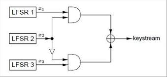
To create a maximal length sequence, the lengths of the three primitive polynomial must be relatively prime pairwise.
Each time a keystream bit is required, the LFSRs produce an output bit as a combination of the output bits of each LFSR.
This combination function called f is defined this way: f(x1,x2,x3) = (x1 and x2) xor ( (not x2) and x3).
Using this boolean algebra trick: (not x2) = (x2 xor 1), we have f(x1,x2,x3) = (x1 and x2) xor (x2 and x3) xor x3.
This keystream generator sequence length is (2^L1 - 1)*(2^L2 - 1)*(2^L3 - 1) assuming L1, L2, L3 are the length of each LFSR.
We can easily simulate this generator with VHDL using a 2-to-1 Multiplexer, output x2 of the 2nd LFSR controlling the multiplexer.
Let's check this quickly:
- if x2, output of LFSR 2, is 0 then f(x1,0,x3) = (x1 and 0) xor (0 and x3) xor x3 = 0 xor 0 xor x3 = x3
- if x2, output of LFSR 2, is 1 then f(x1,1,x3) = (x1 and 1) xor (1 and x3) xor x3 = x1 xor x3 xor x3 = x1 xor 0 = x1
Don't use this type of generator in real world because, even if it's far better than using only one LFSR alone, it's still not secure
and you'll need to build more elaborate constructions using two Geffe generators.
Here is the schematic diagram (made with
Active HDL) and the VHDL code for this simple Geffe keystream generator.
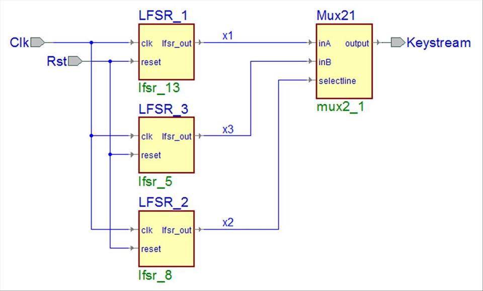
You should copy, paste each VHDL code in your editor and then name each file exactly as shown below:
geffe.vhd, mux21.vhd, lfsr_5.vhd, lfsr_8.vhd and lfsr.13.vhd
Then check that the project design contains the 2-to-1 Multiplexer and the 3 LFSRs. (See the Taps in each code below)
The initial value of each LFSR is initialized to 00...01 in the code but it could and should be change to any binary number.
library IEEE;
use IEEE.std_logic_1164.all;

---- my libraries declarations ----
library CIPHER;

entity geffe is
  port(
       Clk 		:in std_logic;
       Rst 		:in std_logic;
       Keystream 	:out std_logic
  );
end geffe;

architecture geffe_structure of geffe is

---- Component declarations -----

component lfsr_13
  generic(N : integer := 13);
  port (
       clk 		:in std_logic;
       reset 		:in std_logic;
       lfsr_out 	:out std_logic
  );
end component;
component lfsr_5
  generic(N : integer := 5);
  port (
       clk 		:in std_logic;
       reset 		:in std_logic;
       lfsr_out 	:out std_logic
  );
end component;
component lfsr_8
  generic(N : integer := 8);
  port (
       clk 		:in std_logic;
       reset 		:in std_logic;
       lfsr_out 	:out std_logic
  );
end component;
component mux2_1
  port (
       inA 		:in std_logic;
       inB 		:in std_logic;
       selectline 	:in std_logic;
       output 		:out std_logic
  );
end component;

---- Signal declarations used on the schematic diagram ----

signal x1 	:std_logic;
signal x2 	:std_logic;
signal x3 	:std_logic;

begin

----  Component instantiations  ----

LFSR_1 : lfsr_13
  port map(
       clk => Clk,
       lfsr_out => x1,
       reset => Rst
  );

LFSR_2 : lfsr_8
  port map(
       clk => Clk,
       lfsr_out => x2,
       reset => Rst
  );

LFSR_3 : lfsr_5
  port map(
       clk => Clk,
       lfsr_out => x3,
       reset => Rst
  );

Mux21 : mux2_1
  port map(
       inA => x1,
       inB => x3,
       output => Keystream,
       selectline => x2
  );

end geffe_structure;
library ieee;
use ieee.std_logic_1164.all;
entity mux2_1 is
	port(
		inA  			:in std_logic;
		inB  			:in std_logic;
		selectline		:in std_logic;
		output  		:out std_logic
	);
end mux2_1;
architecture behavioral of mux2_1 is
begin
	process(inA,inB,selectline)
	begin
		if selectline = '0' then
			output <= inA;
		else
			output <= inB;
		end if;
	end process;
end behavioral;
library ieee;
use ieee.std_logic_1164.all;
entity lfsr_5 is
 	generic(constant N: integer := 5);
 	port (
	 	clk			:in  std_logic;
		reset			:in  std_logic;
		lfsr_out		:out std_logic
  	);
end entity;
architecture behavioral of lfsr_5 is
 	signal lfsr_tmp			:std_logic_vector (N-1 downto 0) := (0=>'1',others=>'0');
 	---- Taps (primitive polynomial) used [5 4 3 1] ----
	constant polynome		:std_logic_vector (0 to N-1) := "11101";
begin
 	process (clk, reset)
		variable feedback :std_logic;
	begin
		feedback := lfsr_tmp(0);
		for i in 1 to N-1 loop
    		feedback := feedback xor ( lfsr_tmp(i) and polynome(i) );
		end loop;
	if (reset = '1') then
    	lfsr_tmp <= (0=>'1', others=>'0');
	elsif (rising_edge(clk)) then
		lfsr_tmp <=  feedback & lfsr_tmp(N-1 downto 1);
	end if;
	end process;
	lfsr_out <= lfsr_tmp(0);
end architecture;
library ieee;
use ieee.std_logic_1164.all;
entity lfsr_8 is
 	generic(constant N: integer := 8);
 	port (
	 	clk			:in  std_logic;
		reset			:in  std_logic;
		lfsr_out		:out std_logic
  	);
end entity;
architecture behavioral of lfsr_8 is
 	signal lfsr_tmp			:std_logic_vector (N-1 downto 0) := (0=>'1',others=>'0');
 	---- Taps (primitive polynomial) used [8 7 5 3] ----
	constant polynome		:std_logic_vector (0 to N-1) := "11010100";
begin
 	process (clk, reset)
		variable feedback :std_logic;
	begin
		feedback := lfsr_tmp(0);
		for i in 1 to N-1 loop
    		feedback := feedback xor ( lfsr_tmp(i) and polynome(i) );
		end loop;
	if (reset = '1') then
    	lfsr_tmp <= (0=>'1', others=>'0');
	elsif (rising_edge(clk)) then
		lfsr_tmp <=  feedback & lfsr_tmp(N-1 downto 1);
	end if;
	end process;
	lfsr_out <= lfsr_tmp(0);
end architecture;
library ieee;
use ieee.std_logic_1164.all;
entity lfsr_13 is
 	generic(constant N: integer := 13);
 	port (
	 	clk			:in  std_logic;
		reset			:in  std_logic;
		lfsr_out		:out std_logic
  	);
end entity;
architecture behavioral of lfsr_13 is
 	signal lfsr_tmp			:std_logic_vector (N-1 downto 0) := (0=>'1',others=>'0');
 	---- Taps (primitive polynomial) used [13 10 9 4] ----
	constant polynome		:std_logic_vector (0 to N-1) := "1001100001000";
begin
 	process (clk, reset)
		variable feedback :std_logic;
	begin
		feedback := lfsr_tmp(0);
		for i in 1 to N-1 loop
    		feedback := feedback xor ( lfsr_tmp(i) and polynome(i) );
		end loop;
	if (reset = '1') then
    	lfsr_tmp <= (0=>'1', others=>'0');
	elsif (rising_edge(clk)) then
		lfsr_tmp <=  feedback & lfsr_tmp(N-1 downto 1);
	end if;
	end process;
	lfsr_out <= lfsr_tmp(0);
end architecture;
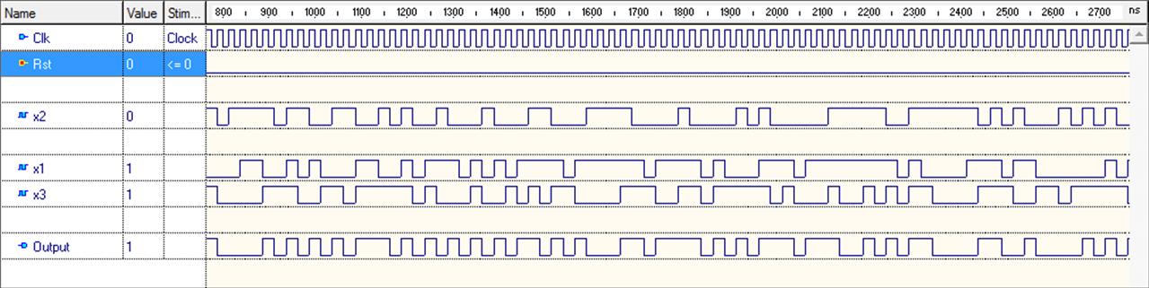
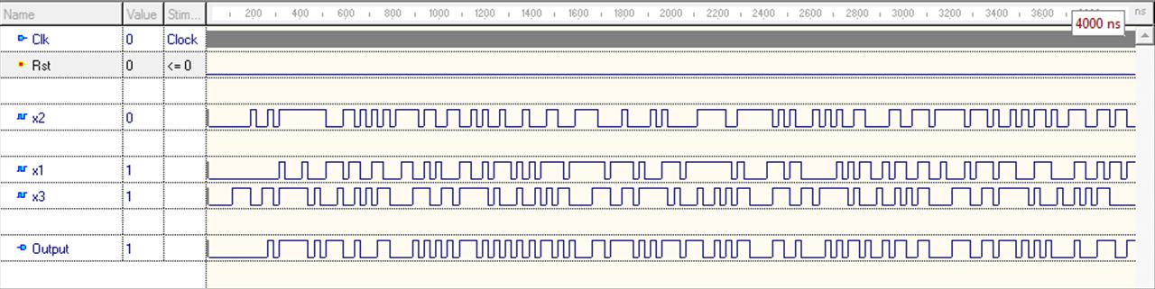
You will get this waveform (2 different scales) if you launch a simulation using
Active HDL software (Clock stimulator: 40Mhz).
2- A more advanced stream cipher: The clock-controlled generator
In nonlinear combination keystream generators (Geffe generator), the linear feedback shift registers are clocked regularly and so all the LFSRs are
controlled by the same clock. To introduce non-linearity in the sequence, we will use the output of one LFSR to control the clocking of one or
more LFSRs. Then these LFSRs become irregularly clocked.
The alternating step generator uses an LFSR R1 to control the stepping or two others LFSRS, R2 and R3. The keystream output results in XORing the
output of R2 and R3.
So let's have a look at this alternating step generator:
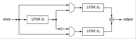
The first LFSR, named R1, controls which one of LFSR R1 or LFSR R2 will be clocked. When R1 is clocked, if its output is 1 then R2 is clocked
and its ouput is XORed with the previous state of R3 which has not been clocked. When R1 is clocked, if its output is 0 then R3 is clocked
and its output is XORed with the previous state of R2 which has not been clocked.
The following steps are repeated until a keystream of desired length is produced.
Don't use this type of generator in real world with small parameters: If you want the generator to have good
statistical properties and be quite secured, the length of the three primitive polynomial must be
relatively prime pairwise and also the length of all LFSRs should be at least 128 bits.
Here is the schematic diagram (made with
Active HDL) and the VHDL code for this alternating step generator.
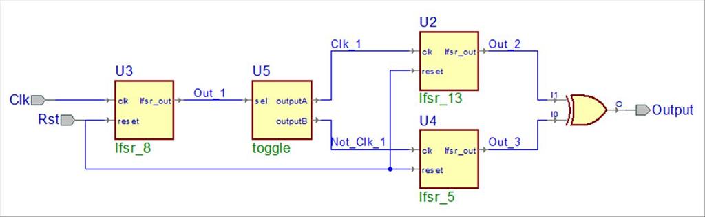
You should copy, paste each VHDL code in your editor and then name each file exactly as shown below:
alter_step.vhd, toggle.vhd, lfsr_5.vhd, lfsr_8.vhd and lfsr.13.vhd
Then check that the project design contains the Toggle component and the 3 LFSRs. (See the Taps in each code below)
The initial value of each LFSR is initialized to 00...01 in the code but it could and should be change to any binary number.
library IEEE;
use IEEE.std_logic_1164.all;

---- my libraries declarations ----
library CIPHER;

entity alter_step is
  port(
       Clk 		:in std_logic;
       Rst 		:in std_logic;
       Output 		:out std_loogic
  );
end alter_step;

architecture alter_step of alter_step is

---- Component declarations -----

component lfsr_13
  generic(N : integer := 13);
  port (
       clk		:in std_logic;
       reset		:in std_logic;
       lfsr_out 	:out std_logic
  );
end component;
component lfsr_5
  generic(N : integer := 5);
  port (
       clk		:in std_logic;
       reset		:in std_logic;
       lfsr_out		:out std_logic
  );
end component;
component lfsr_8
  generic(N : integer := 8);
  port (
       clk		:in std_logic;
       reset		:in std_logic;
       lfsr_out		:out std_logic
  );
end component;
component toggle
  port (
       sel		:in std_logic;
       outputA		:out std_logic;
       outputB		:out std_logic
  );
end component;

---- Signal declarations used on the schematic diagram ----

signal Clk_1 		:std_logic;
signal Not_Clk_1 	:std_logic;
signal Out_1		:std_logic;
signal Out_2		:std_logic;
signal Out_3		:std_logic;

begin

----  Component instantiations  ----

Output <= Out_3 xor Out_2;

U2 : lfsr_13
  port map(
       clk => Clk_1,
       lfsr_out => Out_2,
       reset => Rst
  );

U3 : lfsr_8
  port map(
       clk => Clk,
       lfsr_out => Out_1,
       reset => Rst
  );

U4 : lfsr_5
  port map(
       clk => Not_Clk_1,
       lfsr_out => Out_3,
       reset => Rst
  );

U5 : toggle
  port map(
       outputA => Clk_1,
       outputB => Not_Clk_1,
       sel => Out_1
  );


end alter_step;
library ieee;
use ieee.std_logic_1164.all;
entity toggle is
	port(
		sel			:in std_logic;
		outputA			:out std_logic;
		outputB			:out std_logic
	);
end toggle;
architecture behavioral of toggle is
begin
	process(sel)
	begin
		if sel = '1' then
			outputA <= '1';
			outputB <= '0';
		else
			outputA <= '0';
			outputB <= '1';
		end if;
	end process;
end behavioral;
library ieee;
use ieee.std_logic_1164.all;
entity lfsr_5 is
 	generic(constant N: integer := 5);
 	port (
	 	clk			:in  std_logic;
		reset			:in  std_logic;
		lfsr_out		:out std_logic
  	);
end entity;
architecture behavioral of lfsr_5 is
 	signal lfsr_tmp			:std_logic_vector (N-1 downto 0) := (0=>'1',others=>'0');
 	---- Taps (primitive polynomial) used [5 4 3 1] ----
	constant polynome		:std_logic_vector (0 to N-1) := "11101";
begin
 	process (clk, reset)
		variable feedback :std_logic;
	begin
		feedback := lfsr_tmp(0);
		for i in 1 to N-1 loop
    		feedback := feedback xor ( lfsr_tmp(i) and polynome(i) );
		end loop;
	if (reset = '1') then
    	lfsr_tmp <= (0=>'1', others=>'0');
	elsif (rising_edge(clk)) then
		lfsr_tmp <=  feedback & lfsr_tmp(N-1 downto 1);
	end if;
	end process;
	lfsr_out <= lfsr_tmp(0);
end architecture;
library ieee;
use ieee.std_logic_1164.all;
entity lfsr_8 is
 	generic(constant N: integer := 8);
 	port (
	 	clk			:in  std_logic;
		reset			:in  std_logic;
		lfsr_out		:out std_logic
  	);
end entity;
architecture behavioral of lfsr_8 is
 	signal lfsr_tmp			:std_logic_vector (N-1 downto 0) := (0=>'1',others=>'0');
 	---- Taps (primitive polynomial) used [8 7 5 3] ----
	constant polynome		:std_logic_vector (0 to N-1) := "11010100";
begin
 	process (clk, reset)
		variable feedback :std_logic;
	begin
		feedback := lfsr_tmp(0);
		for i in 1 to N-1 loop
    		feedback := feedback xor ( lfsr_tmp(i) and polynome(i) );
		end loop;
	if (reset = '1') then
    	lfsr_tmp <= (0=>'1', others=>'0');
	elsif (rising_edge(clk)) then
		lfsr_tmp <=  feedback & lfsr_tmp(N-1 downto 1);
	end if;
	end process;
	lfsr_out <= lfsr_tmp(0);
end architecture;
library ieee;
use ieee.std_logic_1164.all;
entity lfsr_13 is
 	generic(constant N: integer := 13);
 	port (
	 	clk			:in  std_logic;
		reset			:in  std_logic;
		lfsr_out		:out std_logic
  	);
end entity;
architecture behavioral of lfsr_13 is
 	signal lfsr_tmp			:std_logic_vector (N-1 downto 0) := (0=>'1',others=>'0');
 	---- Taps (primitive polynomial) used [13 10 9 4] ----
	constant polynome		:std_logic_vector (0 to N-1) := "1001100001000";
begin
 	process (clk, reset)
		variable feedback :std_logic;
	begin
		feedback := lfsr_tmp(0);
		for i in 1 to N-1 loop
    		feedback := feedback xor ( lfsr_tmp(i) and polynome(i) );
		end loop;
	if (reset = '1') then
    	lfsr_tmp <= (0=>'1', others=>'0');
	elsif (rising_edge(clk)) then
		lfsr_tmp <=  feedback & lfsr_tmp(N-1 downto 1);
	end if;
	end process;
	lfsr_out <= lfsr_tmp(0);
end architecture;
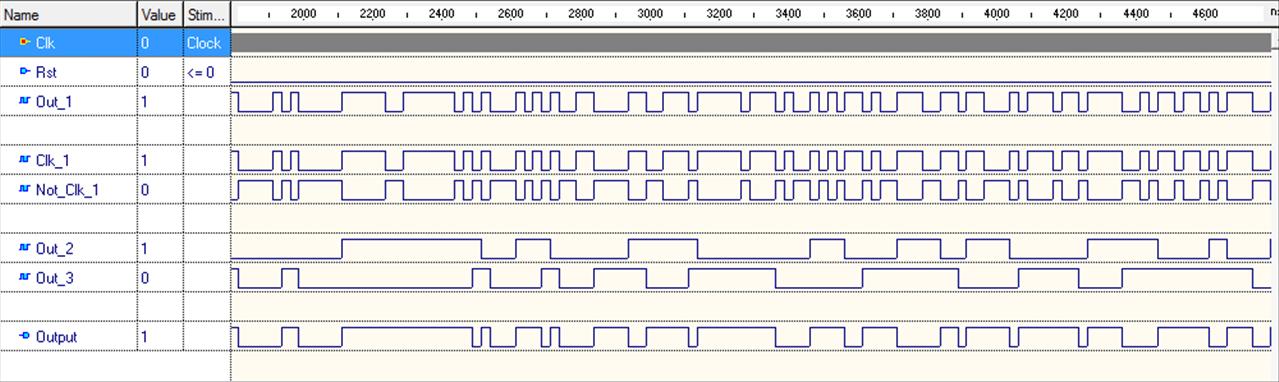
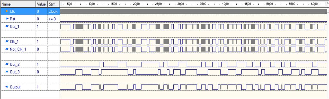
You will get this waveform (3 different scales) if you launch a simulation using
Active HDL software (Clock stimulator: 40Mhz).